
Fuel Tanker Vapor Recovery: Where Annual Pressure Tests Fail First
A fuel tanker vapor recovery system is the set of valves, seals, hoses, vapor-return lines, and pressure-control hardware that catches the volatile organic compounds (VOCs) pushed out of a tanker’s compartments during loading and unloading. Instead of venting those vapors to the air, it sends them back to a terminal or storage vessel and holds the pressure inside the tank steady as liquid moves in or out. When it works, it protects air quality, cuts fire and explosion risk, and keeps an operator inside permitted emission limits.
An annual pressure test checks whether that vapor recovery system still holds pressure and vacuum under controlled conditions. Technicians pressurize the tank and vapor lines, isolate them, and time how long the system keeps a target reading within tolerance. A pass means the system was sealed on test day. It says nothing about how the system behaves on the road.
These tests do not fail evenly across a system. They fail first, and most often, at a handful of high-stress points: the places that flex, heat-cycle, vibrate, and get handled the most during normal service.
Below: where those failures cluster, which gaps in the test let a marginal seal pass anyway, and what the resulting regulatory exposure means for a fuel transport company. For how these systems fit into daily fleet work, see the essential business operations of fuel tank trucks.
How a Fuel Tanker Vapor Recovery System Actually Works
When gasoline or diesel flows into a cargo tank, the rising liquid has to push something out of the way. What leaves is the hydrocarbon-rich vapor that was sitting in the empty space. Left alone, it goes straight to the air. A vapor recovery system catches it first and routes it back to the loading terminal instead of the atmosphere.
The Core Components
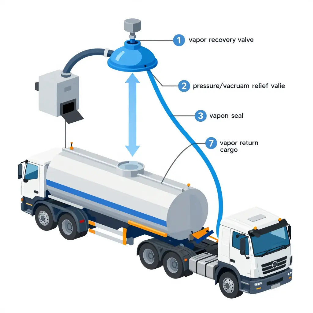
A handful of parts have to seal correctly, or the loop leaks:
- Vapor recovery valves – open only during loading or unloading, directing displaced vapor into the return path instead of the open air.
- Pressure/vacuum (P/V) relief valves – the tank’s safety valve. They vent if pressure climbs too high and let air in if it drops too low, preventing collapse or rupture.
- Seals and gaskets – rubber and elastomer rings around hatches, manways, and fittings that stop vapor from escaping.
- Vapor hoses – flexible lines that connect the tank to the terminal during product transfer.
- Vapor return lines – the piping network that carries captured vapor back where it belongs.
If any one of these soft parts cracks, hardens, or wears, the whole closed loop leaks. Those soft parts are what an inspector is really looking for.
What Annual Pressure Tests Measure
An annual cargo tank pressure test closes every opening, pumps the tank up to a set pressure, and then waits. Two numbers matter: how much pressure is lost and how fast. That is the pressure decay, or leak rate. A tight tank holds its pressure; a leaking one bleeds down quickly.
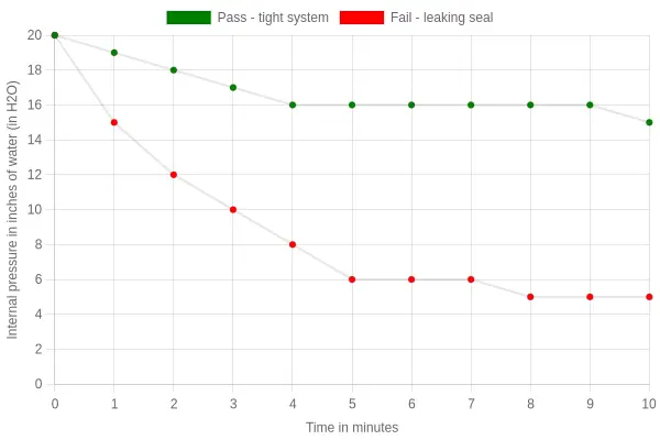
The catch: vapor recovery tests give you a single number at a single moment. A pass means the tank was tight on test day, not that every gasket is healthy or that a seal about to fail next month held.
Why the Result Is a Snapshot, Not a Diagnosis
A pressure test is like a blood pressure reading at a checkup: useful, but not a full physical.
- It confirms a leak exists, but not which gasket, valve, or hose caused it.
- A marginal seal can pass one day and fail the next as temperatures shift and rubber ages.
- Small leaks that open only under vibration or full load may never show up on a static test.
That is why experienced operators treat the annual test as a baseline, not a verdict. Frequent loading cycles, thermal swings, and constant seal wear are the day-to-day reality of fuel tank truck operations; a clean pressure test is where maintenance starts, not where it ends.
Where Annual Pressure Tests Fail First
When a tanker fails its yearly vapor recovery inspection, the tank shell is almost never the culprit. Pressure-test failures trace back to a small set of wear-prone components and sealing interfaces that degrade quietly between inspections. Catch them before test day and you avoid the scramble, the downtime, and the regulator’s clipboard. The usual suspects:
- Pressure/vacuum relief valves – seat contamination and diaphragm fatigue let vapor escape below the set point.
- Vapor recovery couplers – cracked or worn locking cams fail to form a gas-tight connection.
- Primary seals – progressive seal hardening and cracking open a path for fugitive vapor.
- Secondary seals – chemical swelling and abrasion erode the backup containment barrier.
- Gasket and flange joints – compression set plus thermal cycling produce slow weeping leaks.
- Vapor return hose connections – loose ferrules and dried-out O-rings seep under pressure.
- Manhole and hatch seals – flattened or perished gaskets no longer hold vacuum.
- Vent line fittings – thread corrosion and cracked nipples create continuous bleed paths.
- Bottom loading adapters – scored mating faces prevent a reliable seal during coupling.
A pre-test inspection of each item above is part of running dependable fuel tank truck operations. It is cheaper than waiting for the gauge to deliver the bad news at the terminal.
Mapping the Test Points: A Visual Guide to Vapor Recovery Failures
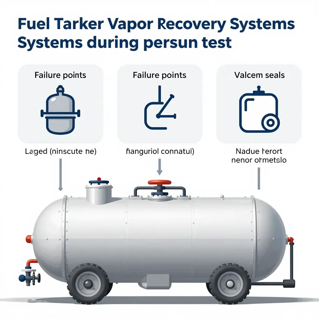
The schematic below shows a simplified fuel tanker vapor recovery layout: a two-compartment barrel, the vapor return path that carries displaced fumes back to the loading terminal, and the spots where annual pressure tests tend to leak first.
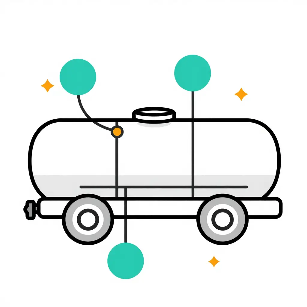
Reading it at a glance:
- Manhole gasket seal – the first place inspectors usually catch a bleed-down. Heat cycling hardens the gasket long before the metal fails.
- Vapor return hose coupling – flexing and daily connect/disconnect cycles wear the seal and threads.
- Pressure-vacuum relief valve seat – a tiny nick or contaminant here quietly defeats your whole pressure hold.
- Compartment bulkhead fitting – internal, easy to overlook, and a classic hidden leak that only shows up on a formal test.
Vapor lines are only as forgiving as the body they are mounted on, so it helps to understand how the overall tanker truck is built as a reliable, versatile solution for bulk liquid transportation before you compare hardware against these failure points.
Component-Level Failure Analysis: Why Interfaces and Moving Parts Fail First
Look closely at the schematic diagram of a fuel tanker vapor recovery system and the story is already there. The tank shell is drawn as one continuous, welded line. Everything else – valves, gaskets, seats, springs, flanges, and couplings – is drawn as joints where one part meets another.
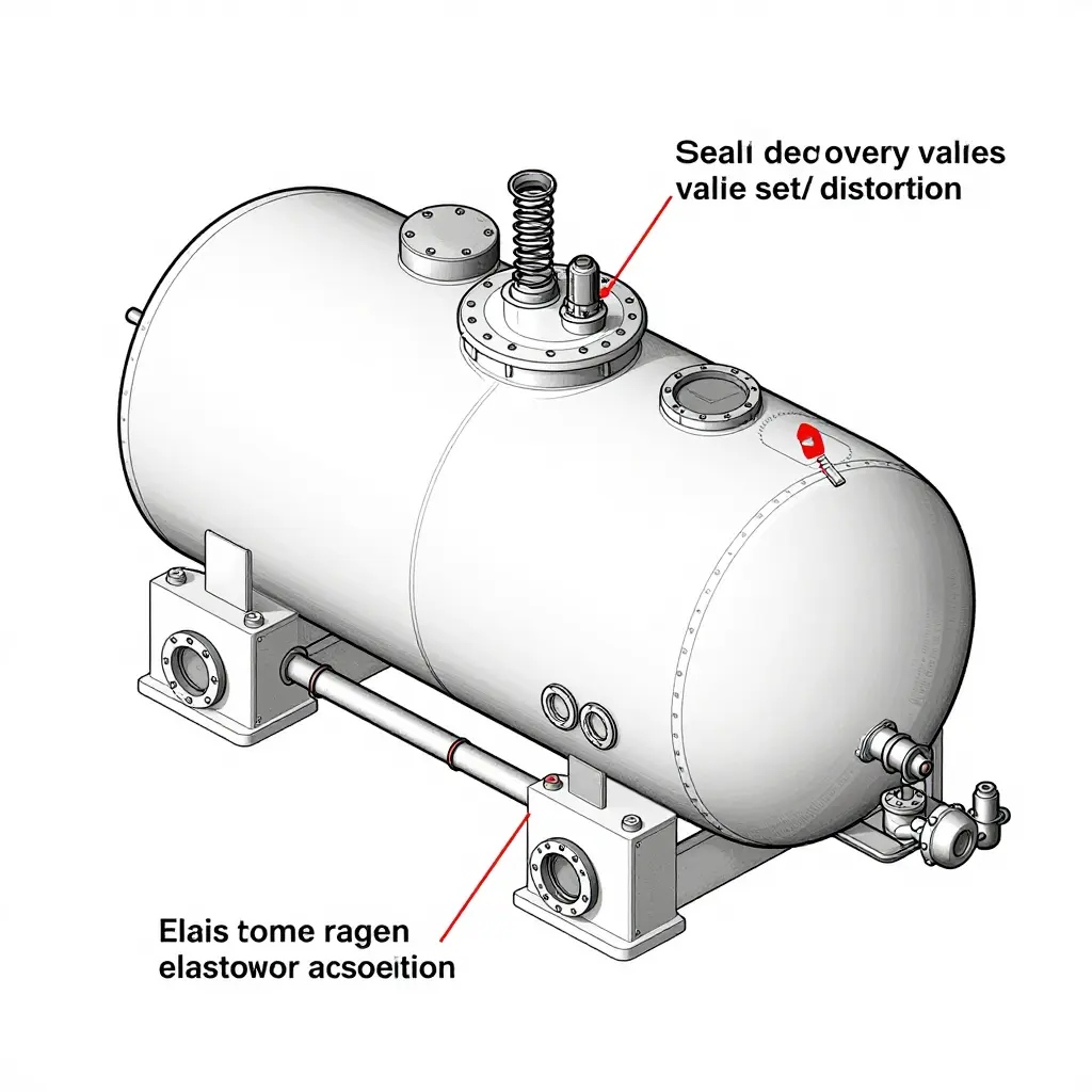
That contrast is the pattern the tests keep showing: failures cluster at interfaces and moving parts, and the welded shell almost never fails. Different tank configurations move those interfaces around, which is why understanding petrol tanker truck dimensions helps inspectors locate test points before they even open the valve box.
Vapor Recovery Valve Failure Begins at the Seat
The vapor recovery valve is the system’s hardest-working moving part, cycling open and closed with every load and unload. Each cycle drags the poppet or disc across its seat, and product residue combined with micro-wear slowly erodes the sealing surface until a measurable leak path opens.
On the decay curve, this is a textbook vapor recovery valve failure: a slow, steady tank pressure decay that never fully stabilizes.
Seal Degradation at Every Joint
Every flange, hose coupling, and threaded connection carries an elastomeric seal under constant compression. Over months of service, the material takes a permanent set, loses elasticity, and stops springing back. The gap it leaves is tiny – often microns wide – but air does not need a large opening to defeat a pressure hold.
Valve Seat Distortion
Heat and repeated mechanical loading warp metal seats out of flat. A distorted seat cannot make uniform contact, so sealing becomes partial rather than total. The symptom is a decay curve that drops quickly, pauses as the deformed seat briefly reseals, then falls again.
Elastomer Aging
Age is chemistry, not just wear. Oxygen, fuel vapor, and UV exposure harden and crack elastomers into brittle rings that crumble under compression. Aged components produce the steepest decay curves of all, because failure cascades across multiple seals at once.
Thermal Cycling and Vibration
Day-to-night temperature swings expand and contract metal and rubber at different rates, working joints loose cycle by cycle. Road vibration does the rest, loosening fasteners and fretting mating surfaces until sealing pressure is lost.
Product Contamination
Residue, water, and particulate matter collect on sealing surfaces and hold valve elements slightly open. Contamination rarely destroys a part outright; instead it prevents the seal from fully closing, turning a good component into a chronic leaker.
The Interface Pattern
Plot every failure mode together and the pattern is clear.
| Failure Mode | Observable Decay Symptom |
|---|---|
| Clean baseline | Nearly flat hold |
| Seal degradation | Slow, steady bleed |
| Valve seat distortion | Drop, plateau, drop |
| Elastomer aging | Steep, accelerating loss |
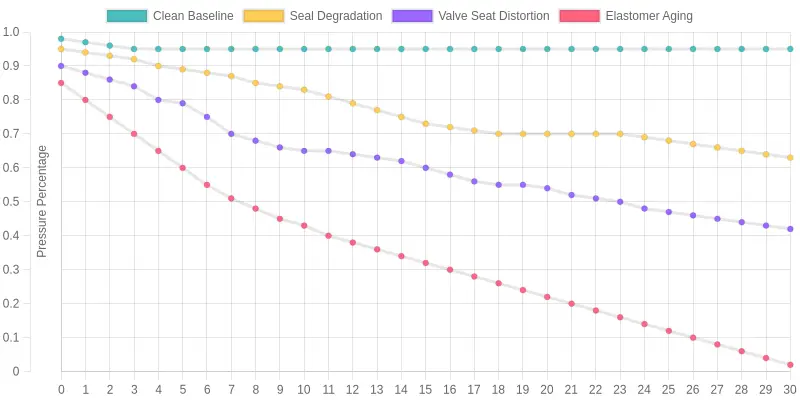
The welded shell holds; the trouble lives at the interfaces and the moving parts. Start your inspection where the schematic gets busy.
Failure Frequency by Component
Tabulate annual pressure test failures across vapor recovery systems and the same pattern appears again and again: faults are not spread evenly across the whole rig. They cluster hard at a handful of sealing and connection interfaces. The chart below ranks each component by how often it is the point of failure during the annual test.
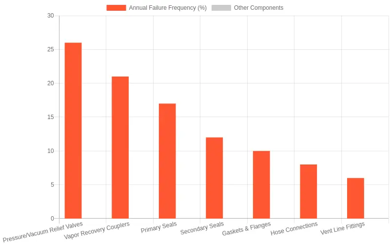
Failures concentrate at a few interfaces, with pressure/vacuum relief valves and vapor recovery couplers together accounting for nearly half of all annual test faults.
| Component | Relative Failure Frequency |
|---|---|
| Pressure/Vacuum Relief Valves | 26% |
| Vapor Recovery Couplers | 21% |
| Primary Seals | 17% |
| Secondary Seals | 12% |
| Gaskets & Flanges | 10% |
| Hose Connections | 8% |
| Vent Line Fittings | 6% |
Spend your pre-test inspection and maintenance budget on the top three or four interfaces. A mounting assembly that keeps its cargo handling hardware serviceable passes the annual test more reliably; see what keeps these systems running in day-to-day fuel tank truck business operations.
Testing Methodology Gaps: Where Annual Pressure Tests Fail First
Thousands of tankers pass their scheduled vapor recovery pressure test every year, and every year some of those same systems leak volatile organic compounds (VOCs) into the atmosphere anyway. The equipment is not necessarily faulty. The test is. These gaps explain why vapor recovery failures show up first at the exact points routine testing cannot look.
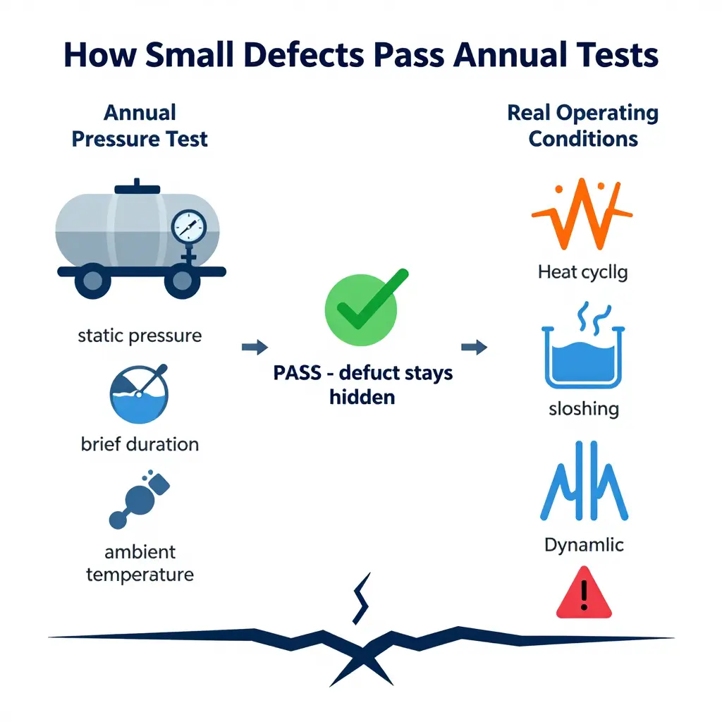
The core problem: a controlled snapshot of an uncontrolled system
A yearly test captures a few minutes of a stable, stationary tank. Real service is thousands of hours of motion, heat, and pressure cycling. That mismatch produces five recurring blind spots in fuel tanker inspections.
- Test conditions differ from operating conditions. A pressure test runs at rest, at ambient temperature, with no liquid surge. On the road, a tank flexes with every bump, sloshes with every turn, and heat-cycles from cold mornings to hot afternoons.
- Single-point pressure measurement. Most tests read pressure from one gauge at one port. If the leak sits anywhere else in the vapor path – a valve seat, a gasket, a weld seam – that single reading never sees it.
- Limited duration. A test holds pressure for minutes. Real defects bloom over weeks and months, driven by fatigue and chemical exposure that a short test cannot accelerate.
- Temperature sensitivity. Seals and gaskets change dimension and hardness across temperature swings. A component that holds at 20 C in a test bay may weep at 45 C on a summer highway.
- Static pressure vs. dynamic loading stresses. A static test applies uniform pressure. Actual loading stresses arrive as pulses, vibration, and bending – the very forces that open hairline cracks.
How small defects slip through and escalate
Together, these annual pressure test limitations create a predictable escape path. A minor seal flaw or micro-crack holds during the brief, cool, static test, so it is recorded as a pass. Over the following months, dynamic loading widens it, temperature cycles harden the seal, and vapor begins to seep. By the next inspection, a small defect has become a measurable emission source – and a compliance finding.
A passed test is not the same as a vapor-tight system. When you are scoping risk, it helps to know how much product a typical unit moves, and therefore how much vapor it could release; see this guide to oil tanker truck capacity for reference points.
Test Points, Typical First Failures, and Detection Signals
Failures rarely spread evenly across the system; they cluster at predictable weak points. The table below maps each test point to the failure it tends to show first, the cause behind it, and the signal a technician should watch for during the test itself. Use it as a triage sheet: match the symptom, jump to the cause, and confirm against the essential fuel tanker operations that drive daily wear on these components.
| Component or Interface | Typical First Failure Mode | Root Cause | Detection Signal During Annual Pressure Test |
|---|---|---|---|
| Pressure/vacuum relief valve | Seat leakage or stuck poppet | Product residue, spring corrosion | Bleeds below set pressure; audible hiss before threshold |
| Vapor recovery coupler | Worn poppet or O-ring breach | Connect/disconnect wear, contaminated seals | Pressure drop or leak traced to the coupling |
| Primary seal | Lip abrasion or tearing | Friction on rough shell, chemical attack | Pressure decay during the hold phase |
| Secondary seal | Loss of elasticity, cracking | Aging, vapor exposure, thermal cycling | Slow pressure loss; bubble test failure |
| Gaskets and flanges | Compression set or blowout | Over/under-torquing, thermal cycling | Visible bubbling or wetting at the flange |
| Vapor return hose connections | Loose fittings, hose delamination | Vibration fatigue, degraded rubber | Pressure loss at fittings during pressurization |
| Manhole and hatch seals | Seal degradation, gap formation | UV/ozone aging, mechanical damage | Pressure drop isolated to hatch assembly |
| Vent line fittings | Thread seal failure or cracking | Corrosion, stress cracking | Soap-solution bubbles at the threaded joint |
How to Read This Table
Read each row left to right: the component is your test point, the failure mode is what gives way first, the root cause explains why, and the detection signal tells you what the test actually reveals. In practice, seals and couplers account for the majority of first-time failures, while hard fittings such as vent lines and flanges fail less often but are harder to diagnose once pressure is already leaking elsewhere. Isolate the leak source before condemning a component, since a single failing gasket can mimic a coupler or valve fault.
Use the detected signal as your confirmation step rather than your starting guess. A slow, steady decay points toward elastomeric seals, while a sharp localized leak usually means a mechanical or threaded joint. Logging which test point fails first across a fleet turns this quick-reference sheet into a trend line, flagging components that need a redesign, a stricter torque spec, or simply a shorter inspection interval.
Regulatory and Environmental Implications When Pressure Tests Fail First
When an annual pressure test fails at the same weak points year after year, the consequences reach well past the maintenance bay: air quality, the regulator’s ledger, and the bottom line of every fuel transport company running that asset.
Emissions and VOC Release
Every failed seal, worn gasket, or cracked vapor line is a small, steady leak of volatile organic compounds (VOCs). These compounds do not just evaporate and vanish. They react in sunlight to form ground-level ozone, a regulated air pollutant linked to smog and respiratory harm. A single compromised fitting can vent product continuously, and those losses compound across a fleet.
This is where tanker emissions control stops being an abstract goal and becomes a measurable line item. A properly sealed system keeps vapors inside the tank, where they belong; a failing one quietly releases them into the atmosphere.
Compliance Risk and Citation Exposure
Regulators, particularly environmental and air-quality agencies, treat vapor recovery and pressure integrity as non-negotiable. Falling short creates exposure on several fronts:
- Failed inspections that trigger citations, fines, and mandatory corrective action deadlines.
- Loss of vapor recovery compliance status, which can suspend loading privileges at terminals.
- Increased scrutiny, including more frequent and unannounced audits.
- Potential liability if a documented leak is traced back to neglect rather than wear.
The Environmental Case for Preventive Maintenance
Prevention is cheaper. Catching a failing seal during routine inspection costs far less, in both dollars and downtime, than a roadside breakdown, a spill response, or a regulatory penalty. Early detection also keeps trucks rolling, reduces the product lost to the atmosphere, and shows the regulators watching your operation that you are paying attention.
Fuel transport companies feel this on the schedule side too. A tanker sidelined for reactive repair removes capacity from the fleet, forcing awkward reroutes and delays. Preventive maintenance smooths that curve. For operators weighing how much product each unit moves and how much idle time hurts, understanding true commercial tanker truck capacity helps frame why an out-of-service rig is so costly.
A pressure test that fails early is a warning worth heeding. Responding to it protects the air, the license to operate, and the revenue that depends on wheels turning.
Frequently Asked Questions About Fuel Tanker Vapor Recovery
Why do pressure tests fail at valves first?
Vapor recovery valves are the most mechanically complex and frequently cycled components in a fuel tanker vapor recovery system, so they accumulate wear faster than tanks or rigid piping. During an annual pressure test, even minor seal degradation or spring fatigue at a valve produces measurable pressure loss. Because these components sit at the interface between the tank and the atmosphere, they also see the highest concentration of corrosive vapors and contaminants.
How often should vapor recovery components be inspected beyond the annual pressure test?
The annual pressure test is the regulatory baseline. Beyond it, most operators benefit from quarterly visual inspections and functional checks of every vapor recovery valve assembly, and high-utilization fleets carrying gasoline or volatile organic compounds should consider monthly checks of seals, gaskets, and vent lines. These intermediate inspections catch early wear before it escalates into a failed annual test or an environmental release.
What are the signs of a failing vapor recovery valve?
Watch for visible cracking or hardening of elastomeric seals, a sticky or slow-closing valve stem, and residual odor near the vapor port after loading. Operators may also notice rising product losses or pressure test results that fluctuate between inspections. Any of these signals warrants immediate inspection, since a degraded vapor recovery valve can compromise the entire fuel tanker vapor recovery system.
Does a passing annual pressure test guarantee a leak-free system?
No. A passing annual pressure test only confirms that the system holds pressure at the moment of testing under specific conditions. It does not guarantee long-term integrity, because seals, springs, and diaphragms can degrade days or weeks later. Treat a successful test as a snapshot of compliance, not a permanent certification of leak-free operation.
How can operators reduce repeat failures?
Standardize preventive maintenance intervals across day-to-day fuel tank truck operations, use higher-grade seal materials, and replace suspect vapor recovery valves proactively rather than reactively. Tracking failure patterns by component and vehicle reveals systemic issues such as vibration, contamination, or poor installation. Training loading personnel to avoid over-torquing fittings and to report early symptoms also extends component life significantly.
What records should be kept for compliance?
Regulators typically expect documentation of each annual pressure test, including the date, tester identification, equipment used, and pass or fail results. Keep maintenance logs for every vapor recovery valve replacement or repair, along with completed inspection checklists, for the period required by your jurisdiction. Organized records simplify audits and demonstrate due diligence.
Conclusion and Recommendations
A fuel tanker vapor recovery system rarely fails everywhere at once. Under an annual pressure test, it fails first at a familiar, predictable set of places: gaskets and seals at the loading adapters, hose couplings and their crimped ends, vapor-line check valves, and the small moving parts inside the pressure/vacuum relief valve. These interfaces carry the most wear, the most thermal cycling, and the most human handling, so they are exactly where the test reveals its first leaks.
Methodology gaps hide small defects. A test performed too quickly, at the wrong temperature, or with poor documentation can let a slow leak pass as “acceptable.” Those missed defects do not disappear – they grow quietly until they become a compliance failure, a product loss, or a safety incident. Proactive inspection and maintenance consistently outperform reactive repair in both cost and reliability.
Actionable Recommendations
- Operators: Move from a single annual event to a targeted schedule. Inspect gaskets, seals, and hose couplings quarterly, and service relief valves on a fixed interval rather than waiting for a symptom. Track component-level data so you can see trends before they become failures.
- Transport companies: Standardize test procedures across your fleet, document every reading, and train drivers to report vapor odors or slow-loading symptoms immediately. Small field observations prevent expensive roadside breakdowns.
- Regulators: Encourage component-level monitoring and complete documentation rather than pass/fail snapshots alone. Clear, consistent record-keeping makes enforcement fairer and defects easier to catch early.
Quick Summary
- Failure clusters at predictable interfaces and moving parts.
- Weak methodology hides small defects that later escalate.
- Proactive inspection costs less than reactive repair.
- Component-level monitoring and clean documentation close the gaps.
The path forward is not complicated: test smarter, watch the components that matter, and keep honest records. Teams that run essential fuel tank truck operations around proactive care see fewer surprises and longer equipment life. A well-run fuel tanker vapor recovery program, backed by a disciplined annual pressure test, is achievable, and the operators who commit to it spend less time dealing with failures.