
Baffle Spacing Fundamentals in Tank Fabrication
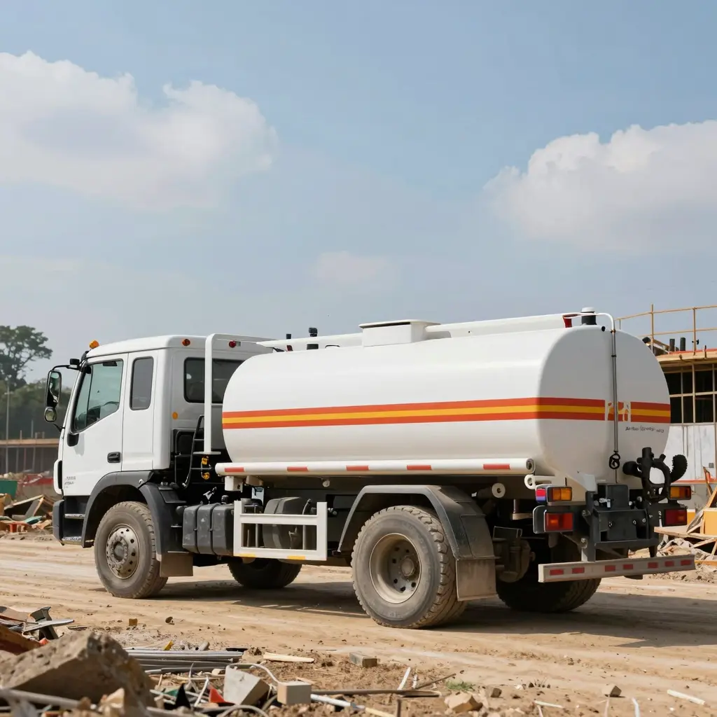
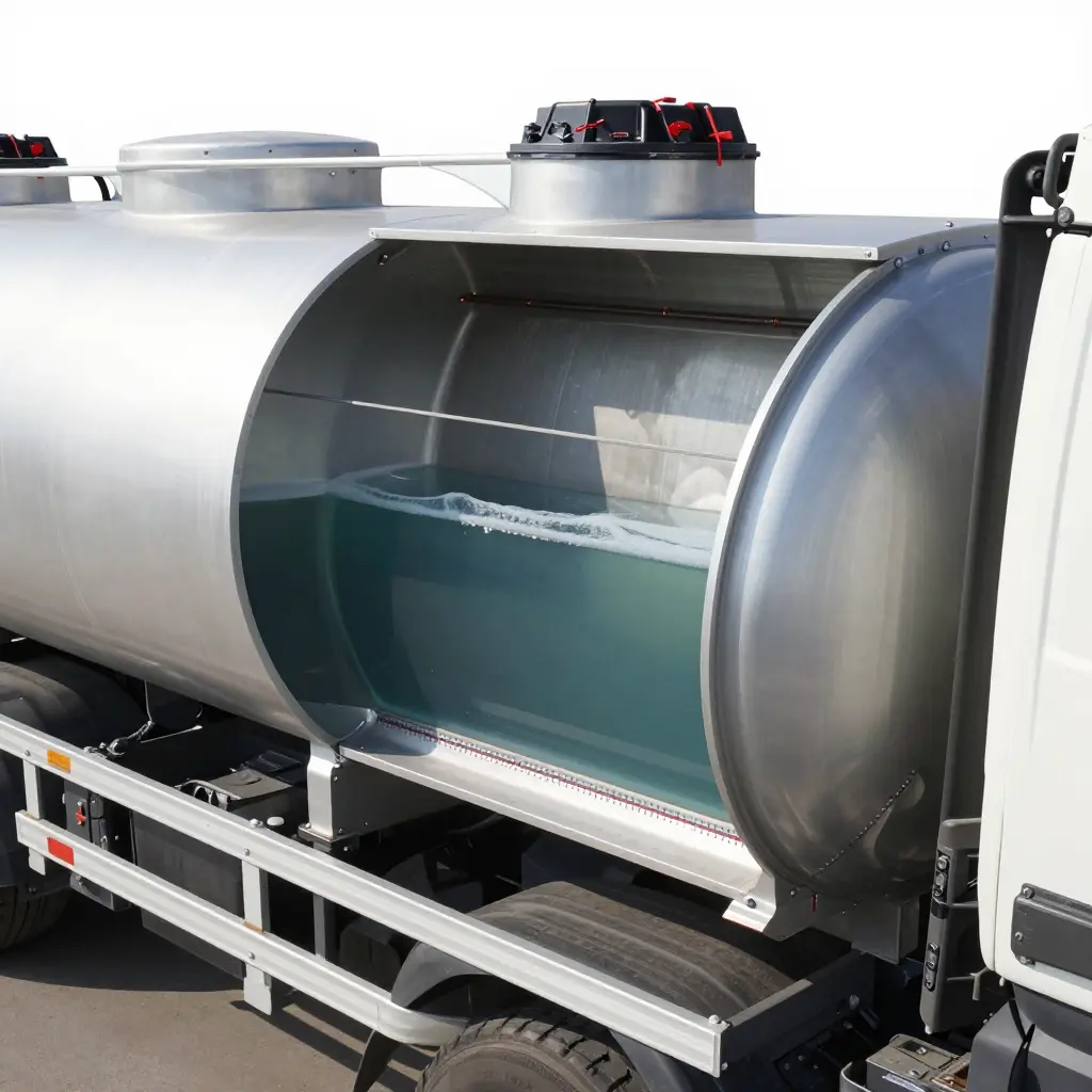
A baffle is a partition welded inside a fuel tanker barrel. It breaks the liquid volume into shorter sections and slows the cargo down as it moves. Baffle spacing — the distance between adjacent partitions — decides how much of that moving liquid’s energy reaches the shell and the internal welds, and how much of it ends up working the chassis. Set the spacing too wide and the tank works harder at every stop and turn; cracked welds, leak claims, and compliance problems follow.
Key Terms You Need to Know
- Compartment: A sealed subdivision of the barrel, closed off by a fluid-tight transverse bulkhead. Each compartment is a separate liquid-tight space used for volume measurement, product segregation, and weight distribution. It is a containment volume, not a pressure vessel.
- Transverse baffle: A vertical plate welded across the barrel’s cross-section, at right angles to travel, that resists liquid moving lengthwise. A baffle is not liquid-tight. It has openings that let fluid pass at a controlled rate, which is what separates it from a compartment bulkhead.
- Slosh load (surge load): The dynamic force produced when liquid shifts forward under braking or sideways in a corner. It is cyclic and impact-like, and it damages weld toes far more than steady hydrostatic pressure does.
Why Baffles Are Welded Into the Barrel
A barrel shell on its own cannot hold a moving liquid mass in check. With no internal partitions and a partial load, the cargo surges end to end at every brake application, loading the shell-to-head welds and shifting weight that the chassis has to fight. Baffles are welded rather than bolted so that surge loads pass into the shell through full-penetration joints. Federal rules reinforce the point: 49 CFR 178.345-4 requires every joint between the shell, heads, baffles, baffle attaching rings, and bulkheads to be welded to Section VIII of the ASME Code.
The Primary Functions of Baffles in a Fuel Tank Truck
- Limit how far the liquid shifts lengthwise during braking, acceleration, and cornering
- Keep the vehicle stable and reduce axle load transfer
- Stiffen the barrel and help the tank body resist twisting
- Work with bulkheads to split one barrel into separate product compartments
- Break the liquid into shorter columns, cutting fatigue cycling at internal welds
- Reduce the sloshing that drives vapor generation and pressure spikes
How Baffle Spacing Is Determined
Three engineering inputs set the spacing:
- Volume and compartment geometry — Spacing sets how much each compartment can carry. Tank batching, legal axle limits, and the product mix all feed into it.
- Load shift control — Closer spacing shortens the liquid column and lowers peak surge force. On partial-load operations, this usually drives the decision.
- Structural loading — Every weld ring concentrates stress. Spacing has to keep the surge impulse low enough for the baffle-to-shell weld to survive millions of fatigue cycles.
Baffle Count, Compartment Geometry, and Surge Loads
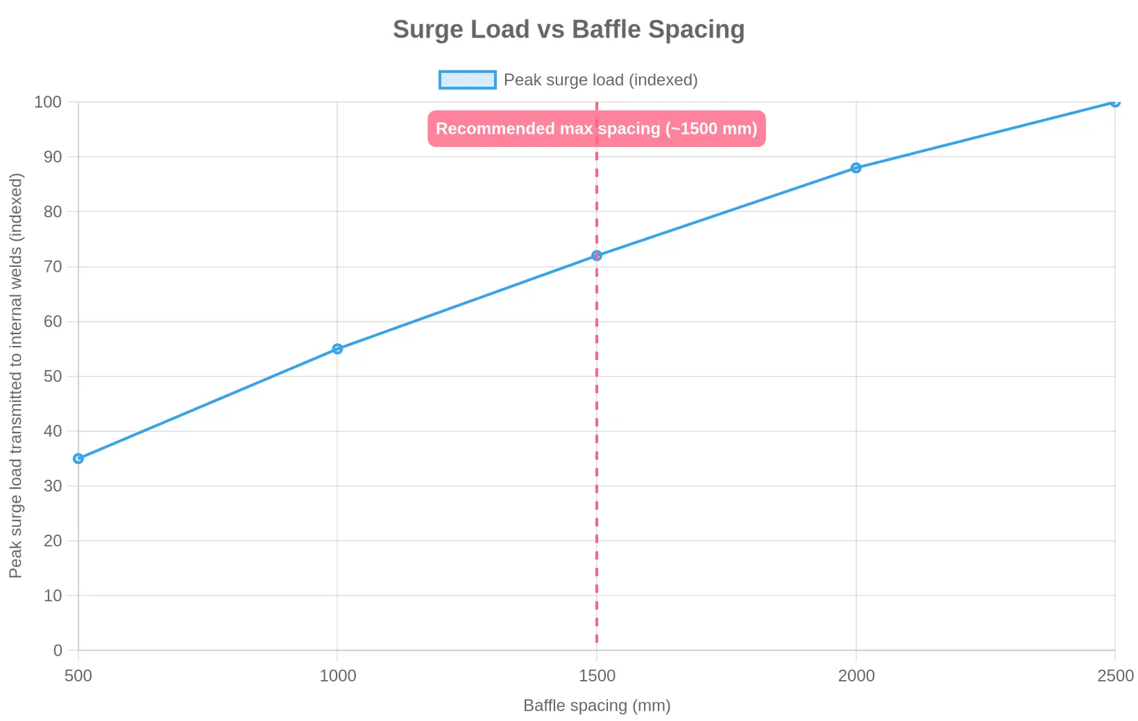
The relationship runs one way. Widen the spacing and the unsupported liquid length grows, so the peak surge load transmitted to internal welds climbs steeply. Add baffles and that energy spreads across more joints — but every new baffle brings more weld passes, more weight, and more inspection points. Fabricators work this trade-off on every build.
For specifiers, baffle count and spacing are fatigue-engineering decisions, not a shortcut to a better fill rate. Break the balance and the failure shows up as a leaking internal weld. That is where how baffle ratings are specified turns into a claim-defining detail.
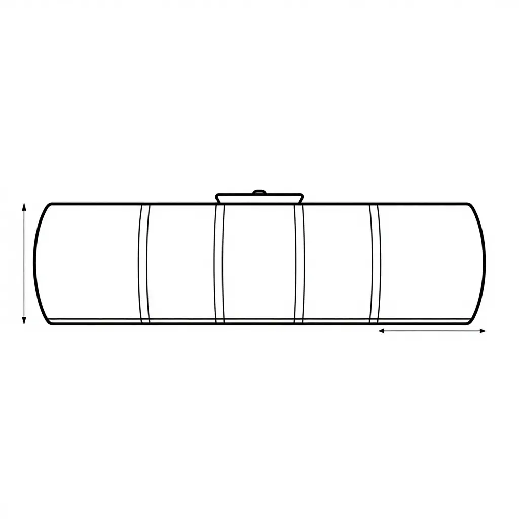
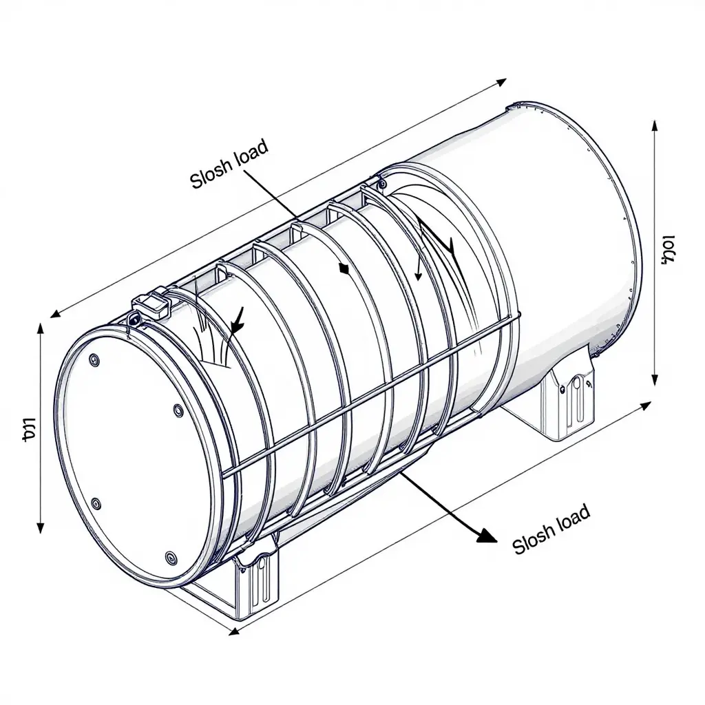
Figure 1. Horizontal cross-section of a fuel tanker barrel with transverse baffles at fixed intervals. The dimension lines mark the spacing between adjacent plates. Tighter intervals spread the longitudinal surge of braking and cornering more evenly across the shell.
Weld Pass Counts and Tank Shell Integrity
Every seam on a fuel tank truck shell is built up one pass at a time. The weld pass counts recorded on the fabrication traveler say as much about long-term durability as the steel specification does. For fabrication engineers and claims adjusters, those numbers predict where a tank will leak — and who ends up paying for it.
Single-Pass vs. Multi-Pass Welding
A single-pass weld deposits all its filler metal in one traversal. It is fast, confines heat input to a single thermal cycle, and suits thin sheet and low-stress components.
On the thicker plate used for fuel tanker barrels and baffles, one pass rarely achieves full penetration through the joint root. Multi-pass welding builds the same joint from several smaller beads laid in sequence, so the operator controls heat input more precisely and reaches penetration a single bead cannot.
The trade-off is unavoidable. Every additional pass adds another thermal cycle, and another chance for residual stress to accumulate.
Why Additional Passes Are Added: Root, Fill, and Cap
Multi-pass joints follow a defined sequence:
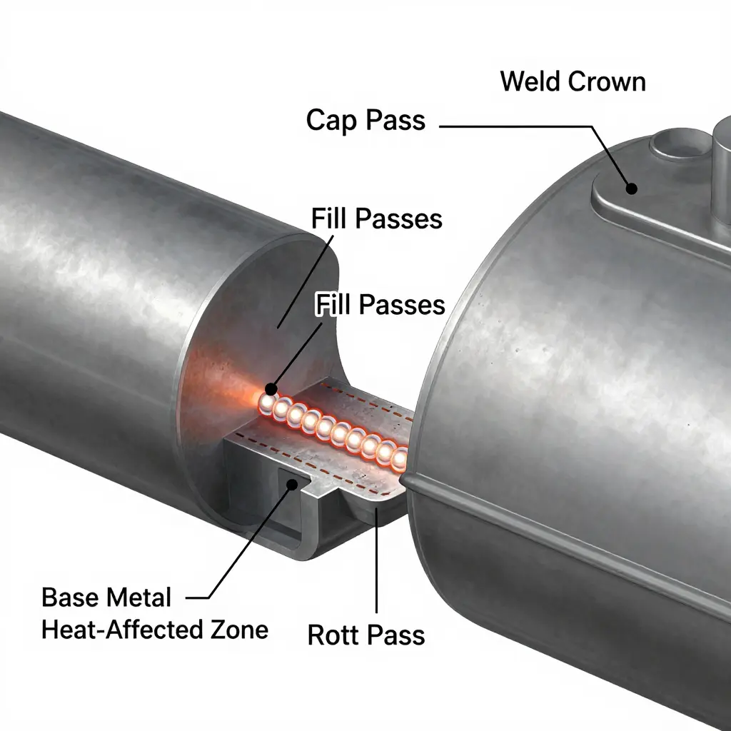
- Root pass — fuses the base metal at the joint bottom and establishes penetration.
- Fill passes — build the joint to near-full thickness, one controlled layer at a time.
- Cap pass — finishes the surface, shapes the crown, and controls profile.
Skipping a pass, or rushing one, is a common reason a fuel tank truck develops a weep at a seam years after delivery. When that weep becomes a spill, it resurfaces in leak claims as a fabrication defect that a documented pass sequence could have prevented.
The Trade-Off: Heat Input, Penetration, and Residual Stress
The tension is straightforward. Higher heat input improves penetration and fusion but concentrates residual stress. Smaller, controlled passes distribute stress, yet they require more steps and introduce more thermal cycling. Balanced correctly, the weld is sound. Imbalanced, it becomes the initiation point for a fatigue crack.
| Attribute | Single-Pass | Multi-Pass |
|---|---|---|
| Penetration | Shallow on thick plate | Full through the root |
| Heat input per pass | High, concentrated | Lower, carefully controlled |
| Residual stress | Concentrated in one cycle | Distributed across passes |
| Fatigue life at baffle joints | Lower | Higher when sequenced correctly |
| Typical application | Thin sheet, low stress | Tank shells, baffle-to-shell joints |
Pass Counts and Fatigue at Baffle-to-Shell Joints
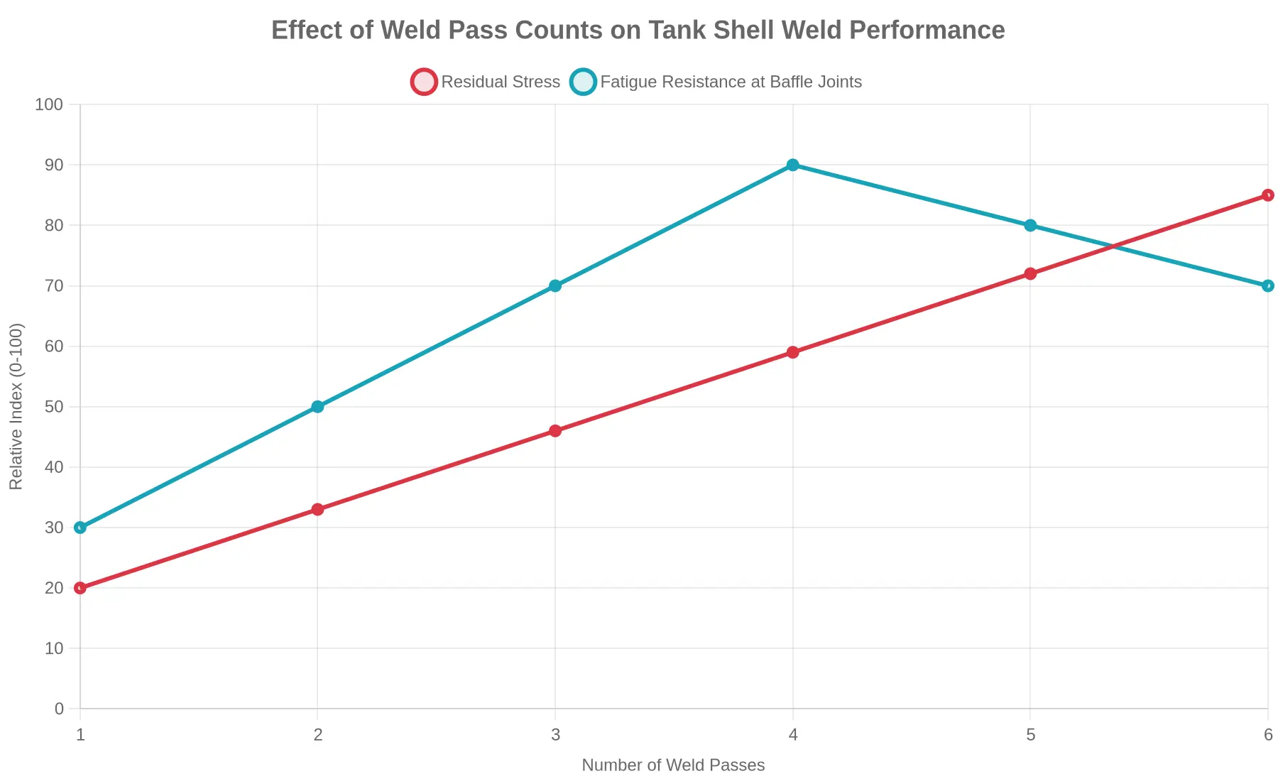
Baffle-to-shell joints are fatigue hot spots because every acceleration and braking event flexes the shell against a rigid internal wall. Too few passes leave incomplete fusion at the root, a hidden notch that grows under cyclic loading. Too many passes at excessive heat input raise residual stress and widen the heat-affected zone, which shortens fatigue life as well.
That is why pass count, not just pass presence, matters in a dispute. Records showing a controlled root, fill, and cap sequence with validated parameters are strong evidence that a failure was operational rather than a manufacturing defect. Insurers reviewing where annual pressure tests fail first can use weld pass counts to trace a leak back to either a fabrication shortcut or genuine service fatigue.
Reading the Weld Records
Open a welding traveler and compare the number of passes against the joint thickness and the qualified procedure. Undocumented or under-counted passes are the earliest warning sign of a tank that will generate future leak claims, and the cleanest line of defense when you have to answer one.
Baffle Spacing and Weld Pass Counts: Specification Comparison
Baffle spacing and weld pass counts are two of the most consequential, and most overlooked, decisions in fuel tank fabrication. Get them wrong and a tank may sail through factory hydrostatic testing only to develop fatigue cracking and seam leaks after a few hundred thousand duty cycles. The table below compares common configurations across duty classes and tank sections. All values are illustrative industry ranges drawn from typical fabrication practice, not guaranteed specifications. Always confirm them against the applicable standard (for example DOT/ASME, ADR, or regional codes) and your builder’s weld procedure specification (WPS).
| Duty Class / Tank Section | Typical Baffle Spacing | Typical Weld Pass Count | Fabrication Rationale | Leak-Claim Risk Indicator |
|---|---|---|---|---|
| Light-duty urban distribution (single compartment, approx. 4,000-8,000 L) | 1.5-1.8 m (5-6 ft) | 2-3 passes | Fewer baffles cut weight and cost; low slosh velocities on stop-start city routes keep surge loads modest | Low |
| Light-duty urban distribution (multi-compartment) | 1.2-1.5 m (4-5 ft) | 3 passes | Compartment heads act as partial baffles; moderate pass count balances burn-through risk on thinner plate | Low-Moderate |
| Long-haul highway (single compartment, steady grade) | 0.9-1.2 m (3-4 ft) | 3-4 passes | Sustained highway slosh demands tighter spacing to limit longitudinal surge; multi-pass seams resist fatigue | Moderate |
| Long-haul highway (multi-compartment, full payload) | 0.9-1.2 m (3-4 ft) | 4 passes | Higher average fill and continuous vibration raise cyclic stress at baffle seams; extra passes add toe reinforcement | Moderate-High |
| High-cycle heavy-duty (continuous duty, steep terrain) | 0.6-0.9 m (2-3 ft) | 4-6 passes, often with a backing strip | Dense baffling and full-penetration welds control surge on grades and maximize fatigue life under high cycle counts | Elevated |
| High-cycle heavy-duty (off-road / aggregate haul) | 0.6-0.8 m (2-2.6 ft) | 5-6 passes | Shock loading and torsional flexing require the most conservative baffling and reinforced seams; highest inspection priority | High |
| Vapor-recovery / sealed section | 0.9-1.2 m (3-4 ft) | 3-4 passes | A sealed vapor space limits slosh but concentrates pressure cycling; pass count is tuned for gas-tight integrity | Moderate-High |
How to read this table
- The Leak-Claim Risk Indicator reflects how often a configuration shows up in fatigue-related leak disputes when it is built to the bottom of its stated range.
- A High rating is not a defect. It means the duty cycle is punishing and the fabrication margin is slim, so weld quality, baffle attachment detail, and non-destructive testing (NDT) coverage matter far more than they do on light-duty builds.
- Baffle spacing and weld pass count should always be specified together. Tight spacing with an under-matched weld schedule, or a heavy pass count with over-wide spacing, can each trade one failure mode for another.
- When specifying a tank, pair tighter baffle spacing with a documented weld pass schedule, and insist on traceable weld maps. This is the same discipline that governs tank baffle ratings in factory specs, where mismatches between baffle ratings and surrounding hardware are a common source of disputes.
- Treat every numeric value here as an illustrative range, not a warranty. Plate thickness, material grade, baffle cutout geometry, and local regulations can all shift the correct figures for a given build.
Factory QC: How Baffle Spacing and Weld Pass Counts Become Documented Evidence
In a competent fuel tank truck factory, quality control leaves a paper trail. Every baffle position and weld pass goes into documents that can be audited years later. For fleet maintenance and compliance managers, reading those records is how you learn what actually stands behind a leak claim.
The foundation is the Weld Procedure Specification (WPS). This document defines the exact process for joining baffle-to-shell and baffle-to-baffle joints: filler metal, amperage, travel speed, pass sequence, and required preheat. A Procedure Qualification Record (PQR) proves the WPS produces sound welds, and each welder holds a qualification record (WPQ) tied to that specific procedure.
Inspection follows every weld. Baffles and longitudinal seams typically undergo radiographic testing (RT), which reveals internal porosity or incomplete fusion across multiple passes, and dye-penetrant testing (PT), which exposes surface-breaking cracks at baffle corners. Together they sit at the core of any rigorous fuel tanker weld inspection.
Dimensional verification is documented with the same care. Inspectors measure each compartment length and baffle spacing against the approved drawing and record the tolerances. Those numbers matter because uneven spacing concentrates sloshing loads and accelerates fatigue cracking at baffle joints.
QC Records a Buyer Should Request
- Weld Procedure Specifications (WPS) with supporting PQRs
- Welder qualification records (WPQ) for every welder who touched the tank
- Radiographic (RT) and dye-penetrant (PT) reports for baffle and shell joints
- Dimensional inspection sheets verifying compartment lengths and baffle spacing
- Mill material certificates and final tank certification paperwork
When a leak dispute escalates, these artifacts become the evidence. RT and PT reports establish whether a joint was sound when it left the factory; pass counts and spacing data show whether the tank met its design intent; and traceability links each weld to a qualified welder. A missing or inconsistent record set weakens a manufacturer’s defense and a buyer’s claim alike. Certification paperwork is also a frequent place for deals to stall, so review it before pickup — discover why tank certification paperwork stalls at pickup.
Reported Leak Claim Frequency by Fabrication Configuration
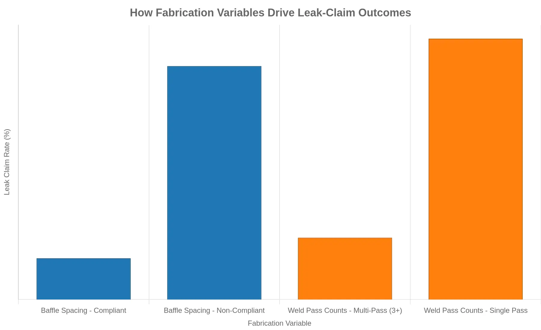
When a fuel tanker springs a leak, the post-mortem almost always traces back to how the barrel shell, baffles, and longitudinal welds were fabricated. Two variables dominate claims investigations: how far apart the baffles sit and how many weld passes were laid down on the shell seams. The chart below shows how those two choices combine to shift the frequency of reported leak claims.
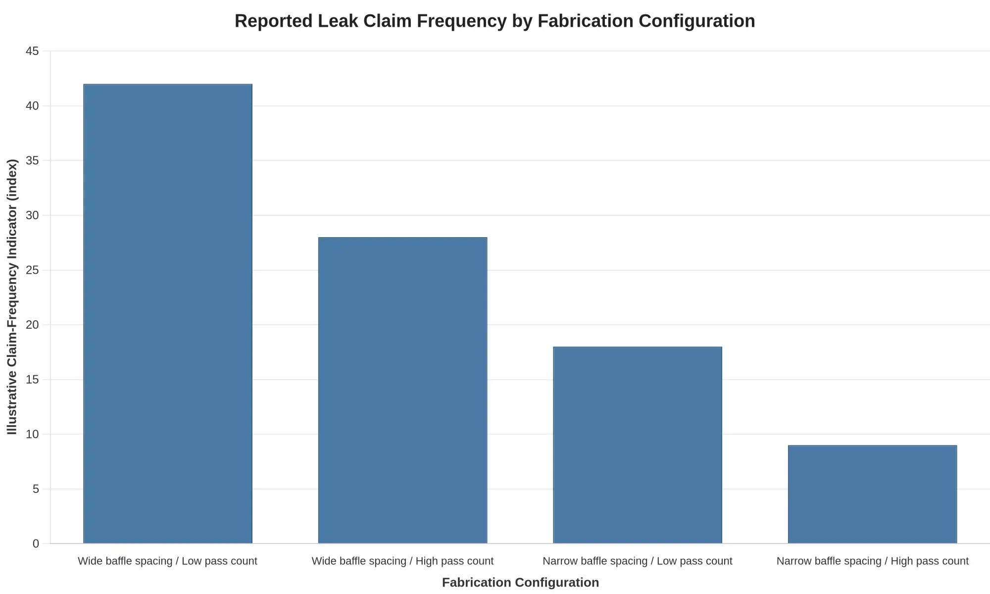
Figure: Reported Leak Claim Frequency by Fabrication Configuration.
Underlying Dataset
The values are an illustrative claim-frequency indicator on an index scale of 0-100. They come from observed patterns in disputed-claim files, comparing how often leaks were alleged across different fabrication configurations, rather than from any universal, statistically sampled population. Treat them as directional, not definitive.
| Fabrication Configuration | Illustrative Claim-Frequency Indicator (index) |
|---|---|
| Wide baffle spacing / Low pass count | 42 |
| Wide baffle spacing / High pass count | 28 |
| Narrow baffle spacing / Low pass count | 18 |
| Narrow baffle spacing / High pass count | 9 |
How to Read the Bars
- Wide baffle spacing / Low pass count (42) — the highest indicator. Wide unsupported shell spans flex more under sloshing loads, and a single-pass weld offers little fatigue reserve at the seam. This is the configuration most frequently named in leak disputes.
- Wide baffle spacing / High pass count (28) — more weld passes add throat thickness and toughness, but the long unsupported span still concentrates dynamic stress.
- Narrow baffle spacing / Low pass count (18) — tighter baffle pitch shortens the unsupported span and cuts flexing, even though the weld itself remains lean.
- Narrow baffle spacing / High pass count (9) — the lowest indicator. Short spans and multi-pass welds together deliver the most fatigue margin against cyclic sloshing.
Why the Two Variables Interact
Baffle spacing and weld pass count are not independent levers. They multiply each other’s effect. A wide span amplifies the bending moment that a thin, single-pass weld has to absorb, so the weakest weld in the weakest layout produces the worst outcome. A buyer who specifies close baffle pitch but still accepts one-pass longitudinal seams likewise leaves fatigue resistance on the table.
For fleet owners and specifiers, the practical move is to read a tanker’s fabrication drawing as a system, not a checklist. Confirm both the baffle pitch and the specified pass count against fatigue-critical seams. For a closer look at how tank construction shapes real-world service life and reliability, see our overview of the tank truck as a reliable solution for bulk liquid transportation.
A Caveat on the Numbers
Claim frequency is shaped by much more than fabrication. Cargo chemistry, operating terrain, maintenance history, and inspection rigor all intervene. The indicator above is meant to isolate the relative influence of the two fabrication variables so that engineering and claims teams can compare configurations on the same footing.
Pre-Purchase Inspection Steps for Baffle Spacing and Weld Pass Counts
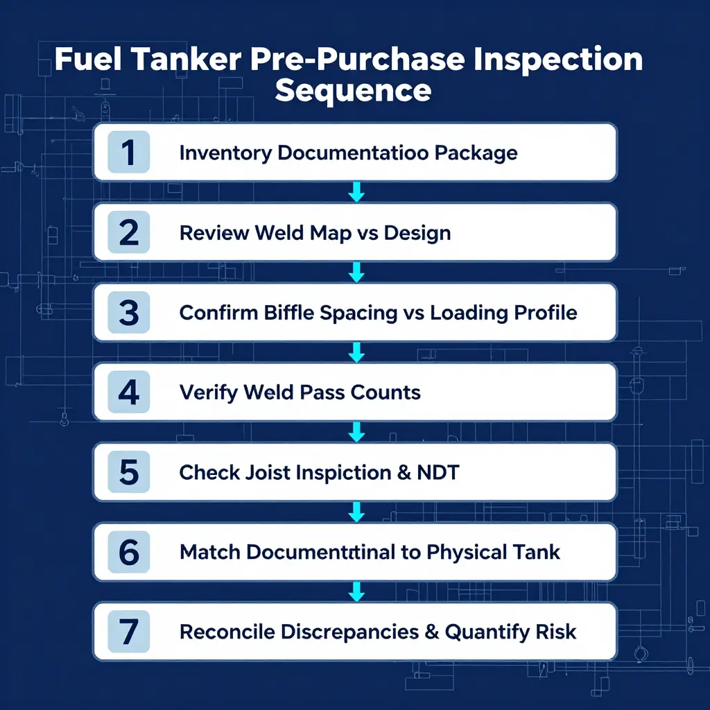
Before a fuel tanker changes hands, the tank has to be read the way it was built: as an engineered vessel whose service life lives in its welds. For buyers, fleet maintenance managers, and insurance adjusters, a disciplined sequence turns shop paperwork and steel geometry into evidence that either supports or defeats fuel tank truck leak claims. Run these steps in order, and document every finding with photographs and signatures.
-
Inventory the full documentation package first. Before touching the ladder, collect the weld map, material mill certificates, joint inspection reports, non-destructive testing (NDT) results, hydrostatic and pressure-test records, and the as-built design drawing. A complete dossier is the backbone of any fuel tanker inspection checklist. Missing pages, unsigned revisions, or photocopied certificates are immediate red flags that shift risk onto the buyer.
-
Read the weld map against the design drawing. Confirm that every longitudinal and circumferential seam, baffle-to-shell weld, and repair callout on the drawing appears on the map. Discrepancies between the two usually mean the tank was modified after certification or built to a superseded revision.
-
Confirm baffle spacing against the actual loading profile. Measure baffle center-to-center distances and compare them with the commodity’s density, the hauling route, and expected dynamic surge. Baffles spaced for static loads will fail under repeated braking surge. If spacing cannot be reconciled with the loading profile, treat it as a structural deficiency, not a cosmetic one.
-
Verify weld pass counts in the weld records. Every seam carries a specified pass sequence — root, hot, fill, and cap. Match the recorded count to the qualified welding procedure specification (WPS). A shortfall typically signals shallow penetration, undercut, or trapped porosity, the exact defects that initiate fatigue cracks and leaks.
-
Check joint inspection reports and NDT coverage. Confirm whether radiographic, ultrasonic, dye-penetrant, or magnetic-particle testing was performed, on which joints, and at what coverage. Pay attention to joints where annual pressure tests fail first. If NDT was sampled rather than performed across critical seams, the risk profile is incomplete.
-
Match documentation to the physical tank, feature by feature. Verify serial and stencil numbers, baffle count, manway and valve configuration, and shell thickness against the paperwork. Photograph each match. A tank whose numbers, baffles, or fittings disagree with its records cannot be reliably traced to its certification.
-
Reconcile every discrepancy and quantify the risk. Log each mismatch — spacing deviation, pass-count shortfall, missing inspection — in a written hold report. Then decide: negotiate a price adjustment, require repair and re-inspection, or walk away. This final step converts engineering findings into a defensible commercial and claims position.
A pre-purchase inspection that follows this sequence does more than validate a purchase. It builds the paper trail that fleet owners and adjusters need when fuel tank truck leak claims surface months later.
How Baffle Spacing and Weld Pass Counts Decide Fuel Tanker Leak Claims
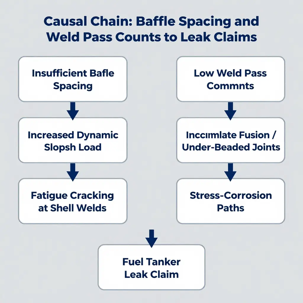
In most disputed fuel tanker leak claims, two manufacturing decisions made long before the truck left the factory decide the outcome: baffle spacing and weld pass counts. Together they set the structural and metallurgical margin a tank carries into years of sloshing, braking, cornering, and thermal cycling.
Why insufficient baffle spacing overloads the shell
Baffles break the barrel into shorter sections and govern where the liquid mass travels under acceleration. Stretch baffle spacing too wide, often to maximize usable volume, and each section holds more free liquid that surges forward and back with every stop and turn.
Engineers call this dynamic slosh load. Wider spacing amplifies the slamming force on the baffle plates and the surrounding shell, concentrating stress at welds and heat-affected zones. Cycle after cycle, that repeated loading drives fatigue cracking. The tank does not fail on day one; it fails at the end of a long accumulation of avoidable stress.
Why low weld pass counts weaken the joints
Weld pass counts describe how many passes were laid to complete a joint. A properly specified seam may require multiple passes to build full penetration and adequate bead thickness. Too few passes leave incomplete fusion, undercut, or under-beaded joints with reduced throat thickness.
These defects are usually invisible at delivery and pass a casual walkaround. They become initiation points only once stress and corrosive fuel reach them.
From micro-defect to leak claim
Fatigue cracks from slosh loading and corrosion paths from weak welds converge. Fuel carries water and corrosive compounds that collect in low spots and attack poorly fused seams, pitting the metal and widening the path a fatigue crack has already started. When a leak finally surfaces, the question becomes causation, and that is where adjusters and engineers reconstruct the manufacturing record.
| Manufacturing variable | Failure mechanism | Claim signal |
|---|---|---|
| Wide baffle spacing | Higher dynamic slosh load | Fatigue cracks at baffle-shell welds |
| Low weld pass counts | Incomplete fusion / thin beads | Corrosion and cracking along seams |
How engineers and adjusters reconstruct cause
During a claim, investigators work backward from the leak. They review baffle drawings, welding procedure specifications, documented pass counts, and non-destructive test reports, then compare observed crack morphology against expected service loading. A crack that starts at a specific weld toe and runs under cyclic load points to slosh-induced fatigue. A branched, discolored crack path points to corrosion-assisted cracking.
Specification choices do not exist in isolation. Fleet buyers chasing maximum payload sometimes accept tighter structural margins, a trade-off explored in our breakdown of petrol tanker truck dimensions. Reading the spec sheet with baffle spacing and weld pass counts in mind is what separates a defensible build from a future dispute.
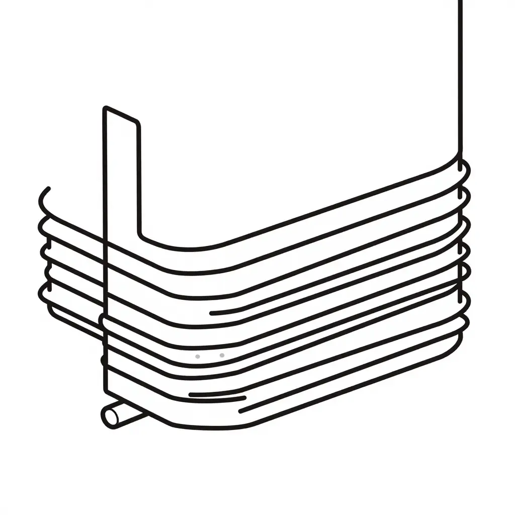
Schematic cross-section of a baffle-to-shell T-joint. The root pass fuses the base of the joint, one or more fill passes build up the throat thickness, and the cap pass seals the top layer. This layered build-up is why baffle welds are counted in passes rather than measured as a single seam.
FAQ: Baffle Spacing, Weld Pass Counts, and Fuel Tanker Leak Claims
1. What baffle spacing is legally or practically appropriate?
Baffle spacing is set by compartment geometry and slosh-load control, not by a single universal number. Most highway fuel tankers place transverse baffles roughly 1.0 to 1.5 meters apart within a compartment, dividing the fluid so surge forces stay within the shell’s design stress. Regulations such as 49 CFR and ISO/EN tank designs emphasize compartment subdivision and structural load capacity rather than an exact spacing figure; 49 CFR 178.345-1 defines a baffle as a non-liquid-tight partition and a bulkhead as the liquid-tight closure that forms a compartment. Practically, tighter spacing dampens slosh better but increases weld count, which is where leaks originate. The right spacing balances surge damping against the number of joints you can reliably inspect.
2. How many weld pass counts are sufficient for a baffle joint?
It depends on plate thickness and joint design. A single pass is rarely adequate for a baffle-to-shell joint that carries dynamic loading.
| Plate thickness | Joint type | Typical passes | Common inspection |
|---|---|---|---|
| 3-4 mm | Fillet | 1-2 | Dye penetrant |
| 4-6 mm | Fillet / groove | 2-3 | Vacuum box, dye penetrant |
| 6-8 mm | Groove | 3-4 | Radiography, dye penetrant |
| Over 8 mm | Groove | 4 or more | Radiography |
For typical 4-6 mm baffle plate, a full-penetration fillet or groove joint usually needs 2-3 passes: a root, a fill, and a cap. Fewer passes risk incomplete fusion.
3. Does pass count alone determine leak risk?
No. Pass count is one variable among several. Leak risk also depends on penetration, porosity, lack of fusion, residual stress, and the quality of post-weld inspection. A three-pass weld with poor travel speed or contaminated base metal can still leak, and a correctly controlled two-pass joint can hold for years. Treat pass count as a process indicator, not a guarantee.
4. How can a buyer verify fabrication records?
Request the Weld Procedure Specification (WPS), Procedure Qualification Records (PQR), welder certifications, pass documentation, and non-destructive testing (NDT) reports. Match serial numbers to the baffle geometry actually installed and confirm the hydrostatic or vacuum test results. If baffle spacing or weld pass counts in the paperwork do not match the tank on the floor, stop the purchase until they are reconciled.
5. How do adjusters decide whether a leak is manufacturing or service related?
Adjusters examine failure location, orientation, and metallurgy. Manufacturing defects typically appear at weld toes, start/stop points, or incomplete penetrations, and often surface early. Service leaks show fatigue cracking, corrosion pits, or impact damage near baffles. The pressure-testing history is decisive here: failures that surface during routine vapor recovery or hydrostatic checks point to fabrication, while damage from overpressure or road impact points to service. Documented pass records and NDT reports, like those reviewed in real pressure-test failures worth understanding, give both buyers and adjusters the traceable evidence needed to settle a claim.
6. What baseline data should a fleet keep for fuel tanker leak claims?
Keep the WPS and PQR on file, log every NDT result, retain baffle spacing drawings, and record operating pressures and inspection dates. This package lets an adjuster separate a fabrication flaw from a service-induced failure without guesswork.
The Verdict: Fabrication Records Are First-Order Evidence
Baffle spacing and weld pass counts are not cosmetic entries on a spec sheet. They are verifiable manufacturing variables that materially determine leak-claim outcomes.
Baffle spacing governs how liquid surges load the shell and internal partitions. When spacing is engineered to the intended service and validated on the drawing, dynamic stress stays within design limits. When it is compressed for cost or copied from an unrelated build, fatigue cycling accelerates and seams open earlier.
Weld pass counts work the same way. A joint welded in a single pass may pass a quick visual check, yet carry porosity, incomplete fusion, or a thin throat that fails under vibration and thermal cycling. Multi-pass procedures build the deposition, refine the grain structure, and tolerate the stresses a loaded fuel tanker actually sees.
For buyers, operators, and adjusters, this reframes where the burden of proof belongs. Fabrication records are first-order evidence, not paperwork to file and forget.
- A fuel tank truck factory that documents weld procedures, pass counts, and baffle layouts gives you a defensible baseline.
- Operators who retain those records can trace a failure to a manufacturing cause or rule it out with confidence.
- Adjusters who request fabrication data resolve leak disputes faster and more fairly than those relying on corrosion speculation alone.
That is why sourcing from established manufacturers matters. Partners with mature welding controls and auditable documentation produce tanks whose claim history is explainable. To see which builders consistently meet that bar, review this breakdown of the top truck fuel tank manufacturers.
Specify baffle spacing and weld pass counts explicitly, verify them against fabrication records, and treat those records as primary evidence in any leak investigation. The factories that control these two variables control their claim outcomes, and so do the buyers, operators, and adjusters who know to check.